


Page 48 - Demo
P. 48
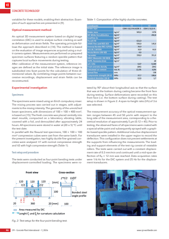
CONCRETE TECHNOLOGY46 CPI %u2013 Concrete Plant International %u2013 1 | 2026 www.cpi-worldwide.comvariables for these models, enabling their abstraction. Examples of such approaches are presented in [9].Optical measurement methodAn optical 3D measurement system based on digital image correlation (DIC) is used to analyse surface cracking as well as deformation and strain fields. The operating principle follows the approach described in [14]. The method is based on the evaluation of image sequences acquired using a multi-camera system. Measurements are performed on prepared specimen surfaces featuring a random speckle pattern that captures local surface movements during testing.After calibration of the measurement system, reference images are defined as the initial state. The reference image is subdivided into facet points for the calculation of three-dimensional values. By correlating image points between successive recordings, displacement and strain fields can be reconstructed.Experimental investigationSpecimensThe specimens were mixed using an Eirich compulsory mixer. The mixing process was carried out in stages, with adjustments to the mixing intensity. The geometry of the unnotched beam specimens, with dimensions of 100 %u00d7 100 %u00d7 400 mm%u00b3, is based on [15]. The fresh concrete was placed centrally into steel moulds, compacted on a laboratory vibrating table, covered with a foil, and demoulded after approximately 24 hours. All specimens were stored in water at (20 %u00b1 5) %u00b0C until the test date. In parallel with the flexural test specimens, 100 %u00d7 100 %u00d7 100 mm%u00b3 compression cubes were cast from the same batch. For the present investigation, two highly ductile fine-grained concretes were analysed: V1 with normal compressive strength and V2 with high compressive strength (Table 1).Test setup and procedureThe tests were conducted as four-point bending tests under displacement-controlled loading. The specimens were rotated by 90%u00b0 about their longitudinal axis so that the surface that was at the bottom during casting became the front face during testing. Surface deformations were recorded on this front face (i.e. the bottom surface during casting). The test setup is shown in Figure 2. A span-to-height ratio (l/h) of 3.6 was selected.The measurement accuracy of the optical measurement system ranges between 45 and 50 %u00b5m/m with respect to the long side of the measurement area, corresponding to a theoretical resolution of approximately 5 %u00b5m (0.12 %u00d7 45). Prior to testing, the observed faces of all specimens were coated with a special white paint and subsequently sprayed with a graphite-based speckle pattern. Additional inductive displacement transducers were installed in the upper region to record the deflection. This configuration does not prevent settlements at the supports from influencing the measurements. The loading and support elements of the test rig consist of rotatable rollers. The tests were carried out with a constant displacement rate of 0.3 mm/min and continued until a mid-span deflection of %u03b4fl = 12 mm was reached. Data acquisition rates were 1/6 Hz for the DIC system and 25 Hz for the displacement transducers.Fig. 2: Test setup for the four-point bending test.Table 1: Composition of the highly ductile concretes.


