


Page 50 - Demo
P. 50
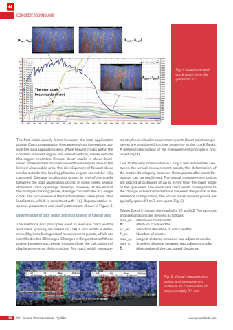
CONCRETE TECHNOLOGY48 CPI %u2013 Concrete Plant International %u2013 1 | 2026 www.cpi-worldwide.comThe first crack usually forms between the load application points. Crack propagation then extends into the regions outside the load application area. While flexural cracks within the constant moment region are almost vertical, cracks outside this region resemble flexural-shear cracks in shear-dominated zones and are inclined toward the mid-span. Due to the limited observable area, the development of flexural-shear cracks outside the load application region cannot be fully captured. Damage localization occurs in one of the cracks between the load application points. In some cases, several dominant crack openings develop; however, at the end of the multiple cracking phase, damage concentrates in a single crack. The occurrence of the fracture stress takes place after localization, which is consistent with [16]. Representative response parameters and crack patterns are shown in Figure 4.Determination of crack widths and crack spacing in flexural testsThe methods and principles used to evaluate crack widths and crack spacing are based on [14]. Crack width is determined by introducing virtual measurement points, which are identified in the 2D images. Changes in the positions of these points between successive images allow the calculation of displacements or deformations. For crack width measurements, these virtual measurement points (facet point components) are positioned in close proximity to the crack flanks. A detailed description of the measurement principle is provided in [14].Due to the very small distance - only a few millimetres - between the virtual measurement points, the deformation of the matrix developing between these points after crack formation can be neglected. The virtual measurement points are placed at distances of up to 3 mm from the lower edge of the specimen. The measured crack width corresponds to the change in horizontal distance between the points. In the reference configuration, the virtual measurement points are typically spaced 1 to 3 mm apart (Fig. 5).Tables 2 and 3 contain the results for V1 and V2. The symbols and designations are defined as follows:max_ Maximum crack width. Medium crack widths.SD_ Standard deviation of crack widths.N_ Number of cracks.max_sr: Largest distance between two adjacent cracks.min_sr: Smallest distance between two adjacent cracks. sr: Mean value of the calculated distances.Fig. 4: Load-time and crack width-time diagrams for V1.Fig. 5: Virtual measurement points and measurement distance for crack widths of approximately 0.1 mm.


