
Page 114 - Demo
P. 114
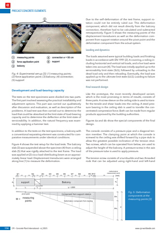
PRECAST CONCRETE ELEMENTS114 CPI %u2013 Concrete Plant International %u2013 6 | 2025 www.cpi-worldwide.comDevelopment and load-bearing capacityThe tests on the test specimens were divided into two parts. The first part involved assessing the practical installability and adjustment options. This part was carried out qualitatively after discussion and evaluation, as well as description of the problems. A load test was then carried out to determine the load that could be absorbed at the limit state of load-bearing capacity and to determine the deflection at the limit state of serviceability. In addition, the natural frequency was examined by applying a hammer test.In addition to the tests on the test specimens, a balcony with a conventional separating element was constructed for comparative measurements under identical conditions.Figure 4 shows the test setup for the load tests. The balcony slab (3) was suspended above the specimen (4) from a ceiling slab (5) that was rigidly attached to the test frame. The load was applied at (2) via a load-distributing beam as an approximately linear load. Displacement transducers were arranged along line (1) to measure the deformation.Due to the self-deformation of the test frame, support rotation could not be entirely ruled out. This deformation component, which did not result directly from the balcony connection, therefore had to be calculated and subtracted retrospectively. Figure 5 shows the measuring points of the displacement transducers as well as the deformation component from support rotation around the pivot point and the deformation component from the actual system.Loading and dynamicsThe loads assumed were typical building loads and finishing loads in accordance with EN 1991 [2]. A covering, a railing including horizontal and vertical rail loads, and a live load were taken into account [4]. The load was initially applied up to the serviceability limit state (SLS), followed by unloading to the dead load only and then reloading. Eventually, the load was applied up to the ultimate limit state (ULS). Loading to failure was not performed.Final research designLike the prototype, the most recently developed variant, which is the most promising in terms of results, consists of three parts. A screw sleeve on the ceiling side is used to transfer the tensile and shear loads into the ceiling. A steel pressure bearing in the ceiling slab is used to transfer the concentrated compressive force. Both can be made from regular products approved by the building authorities.Figures 6a and 6b show the special components of the final design.The console consists of a pressure pipe and a diagonal tension member. The clamping point at which the console is screwed to the ceiling was shifted forward by a pipe stub to allow the greatest possible inclination of the tension strut. Two screws, which can be operated from below, are used to adjust the height of the balcony. A pressure screw in the axis of the pressure tube is used to apply pressure.The tension screw consists of a turnbuckle and two threaded rods that can be adjusted using right-hand and left-hand Fig. 4: Experimental set-up [3]: (1) measuring points; (2) force application point; (3) balcony; (4) connection; (5) supportFig. 5: Deformation components at the measuring points [3]
