


Page 140 - Demo
P. 140
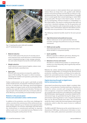
PRECAST CONCRETE ELEMENTS138 CPI %u2013 Concrete Plant International %u2013 1 | 2026 www.cpi-worldwide.com%u2022 Material reductionThinner shells reduce the amount of concrete and cement required. Even small reductions in shell thickness result in substantial savings in mass, energy consumption and carbon footprint across the entire wall surface.%u2022 Weight reductionLower element masses improve logistics, reduce crane loads and shorten assembly times.%u2022 Space gainSlimmer wall cross-sections increase the usable floor space of the building. This aspect is a direct monetary advantage for builders and operators, particularly in residential construction.Carbon reinforcement can be used in wall shells as textile surface reinforcement, as load-path-oriented yarn layers or in the form of individual rods. Openings, electrical/installation zones, edges and support areas can be functionally differentiated by zone-specific reinforcement densities. The basic design principle of the double wall is thus continued, while material efficiency and durability are fundamentally improved.Robotics in the precast plant: Precise and automated carbon reinforcementIn addition to fire protection, one of the main challenges for carbon concrete is the cost structure of the reinforcement systems. Carbon material is up to 15 times more expensive than steel per kilogram. An economic advantage only arises when the reinforcement is manufactured precisely as required, without waste and in an automated process. Robotics is the decisive prerequisite and key factor for this.A central process is robot-assisted direct yarn placement. Carbon fibres are drawn from coils, guided under defined tension and positioned fully automatically according to a digital placement plan. The robot can deposit fibres in a straight line or curved, guide them around openings or orient them along load paths. The layer is then fixed in place %u2013 for example, by impregnation, thermal activation or embedding in a thin matrix system. The result is a reinforcement that does not come from a standard catalogue, but fits the geometry and loads of the respective wall components exactly, thus representing a mass customisation approach that allows economical batch-size-one production in the construction industry.The following industrial benefits result for the semi-precast wall:%u2022 High dimensional and positional accuracyPosition tolerances can be systematically reduced; concrete coverage and positional accuracy are reliably maintained.%u2022 Stable process qualityAutomated placement minimises human factors and reduces variation in component quality.%u2022 Cycle capabilityRobotics operates in defined cycle times, allowing it to be integrated into circulation as a serial process.%u2022 Reduction of errors and reworkDeviations in reinforcement position or component geometry occur less frequently, which significantly reduces scrap and rework.Robotics for carbon reinforcement production enables a conceptual reorganisation of manufacturing: Reinforcement production, handling, insertion and fixing can be easily integrated into automated process modules. This can be a key competitive factor given the shortage of skilled personnel.Digital planning through to digital twins: End-to-end process chainAutomated manufacturing requires digital, consistent data. Product- and production-oriented planning is therefore essential for carbon concrete wall components. Parametric tools and generic component models allow wall types that are compliant with production to be defined at an early stage. Shell thicknesses, opening grids, connection details and reinforcement logic are generated during the design and implementation planning phases in such a way that production data can be derived directly from them. This consistently avoids the classic media discontinuity between planning and production, which is often the cause of errors or inefficient re-planning.The BIM model (IFC files) serves as the central data source. In downstream CAM steps, reinforcement information is translated into robot paths, placement parameters and process Fig. 3: Inserting the outer shell with insulation and 3rd reinforcement layer


